Tuesday, March 8, 2016


Pixie QRP CW Transceiver Kit Project -

Here is the schematic and photos of the completed Pixie. These are very inexpensive - about $7.00 on Amazon, and as little as $3.56 on eBay including shipping direct from China! These crystal controlled QRP (and QSK) transceivers use a minimal number of parts and the transmitter produces a respectable, stable signal with an output of about one Watt depending on supply voltage.  The receiver is, let's say, "Hi-Fi". High fidelity is a great thing for music, but for CW maybe not so much.  I will try to explain:

The Pixie is a direct conversion CW transceiver.  Referring to the schematic diagram, the Y1 crystal oscillator  Q1 transistor is always powered. On Transmit, closing the telegraph key powers the single stage power amplifier Q2 transistor by grounding the emitter and amplifies the crystal oscillator output. It has simple QSK, since closing the key also shorts the audio amp LM386 input to mute audio.  

The amplified transmitter signal is fed thru the Pi output filter to a 50 ohm antenna and about 800mW is produced with a 12V power supply. Transmitter works fine, and it is rock bound without adjustment.  Carl, WB0CFF recorded my Pixie, and I recorded John's, K9KEU Pixie: since the oscillator is always on, there is no chirping common to some other one or two transistor transmitters. (Link to the recordings below.) 

On receive, whenever the key is open, the transmitter power amp circuit is used as the receiver detector.  Received signals come from the antenna in thru the Pi filter. The emitter current to the PA  transistor Q2 is limited by emitter resistor R5 and the power amp base-emitter junction is used as the detector.  Input RF signals are mixed with the crystal oscillator signals then amplified by LM386 audio amp IC into a pair of earbuds or headphones. 

There is no audio filtering, so the product of ALL received signals in the 40m band are fed into the audio amp and one is treated to full Hi-Fidelity reception!  As an added bonus, DC receivers hear both sidebands, so one will hear at least 20kHz of band simultaneously, 10 or more kHz above AND below the transceiver's frequency!  The little trimmer pot W1 provides about 1kHz of adjustment for the receiver's offset.  

Transmitter and receiver tests are here, along with more detailed infornmation including the recordings by Carl and of John's Pixie: https://youtu.be/oNu0kqH5Jnw?list=PLFiIJJI5T2wfSfddvYLS84k7x97pj-we8
 
This kit has only 7.023 MHz crystals. So a ham in the USA must have an Extra Class radio license to operate one on the air.  That is probably a good thing, because if a novice built one, they would be likely be totally confused by plethora of signals on other frequencies - none of which they could ever work using the Pixie.  At least, in the Extra Class portion of the band (below 7.025 MHz in USA), the guy building and using it should theoretically understand the concept and not be disappointed in the results! But in any case, I suppose a cheap little kit like this is a motivational project that might stimulate thinking or even  lead to other more practical QRP transceiver kits like an MFJ Cub or Pacific PFR3.

73,
Lynn

Friday, November 29, 2013

Schematic Diagram for Joe's Reflex Regen Receiver Project!

You may have seen how well Joe's Reflex Regen Receiver plays at www.YouTube.com/NG9D.  Here is the schematic diagram in higher resolution!
73, Lynn
NG9D

Tuesday, January 4, 2011

Packaging a T1056 Receiver Kit


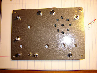
Here are a few photos of project enclosures made for the Ten Tec amateur radio receiver kits, model T1056. A Radio Shack enclosure is used, with an aluminum front panel and plastic cabinet.


Basically, the process involves soldering components onto the printed circuit board and then measuring the completed board before laying out the hole pattern and drilling the front panel. No drilling is required on the plastic case. The height of holes for controls depends on the stand-off supports you use. The supports are also available at Radio Shack.

If you keep the control potentiometers soldered directly to the PC board, then the holes are all aligned and the spacing is set by the printed circuit board. Or, instead of soldering the pots to the board you can use jumper wires to locate the controls wherever you want on your panel. I decided to keep all the pots soldered directly to the board, except for the main tuning controls.


Measure twice before drilling. Mark the panel and use a sharp center-punch on each hole centerline. The center-punch helps keep the drill bit in the correct location when cutting the holes. After center-punching, I drilled small pilot holes before drilling the final larger holes.


After all the drilling is done, make a trial fit-up of all switches, jacks, indicator light and control panel to cabinet. After you are satisfied that all the parts fit properly, then disassemble completely. Wash the panel with liquid soap to remove any dirt or oil.

Completely rinse and dry (I use a hair drier).

Only after the panel is completely clean and dry, then finish with two light coats of spray paint. Allow the panel to air-dry overnight (or longer) before handling to avoid fingerprints.


After the panel is dry, then you can mount the speaker to the panel using two-part epoxy adhesive.


After the speaker is installed, reassemble all the parts. You can then attach pressure adhesive rubber feet to the cabinet. The rubber feet give the radio a solid support and prevent it from sliding around your operating table when you adjust the controls. The yellow radio works on the 40 meter ham band.


You can also paint the plastic cabinet. Be sure to wash and dry it before painting. Allow the cabinet to completely dry before assembling. Attach the rubber feet to the cabinet after the paint is thoroughly dry. The gray radio is a 20m receiver.


There are other packaging options. Ten Tec sells several all-aluminum cabinets that also make nice enclosures.

73 de NG9D


Monday, August 23, 2010

Camping (and Ham Radio)


We certainly enjoyed camping this weekend at Starved Rock State Park!

The limited space doublet antenna with the homebrew parallel wire transmission line worked well on 80 thru 17 meters.

The 50 foot (15m) long doublet was supported at the center with 3 pieces of 5 ft long TV mast. And the ends of the antenna were supported with 12 foot long, telescoping aluminum painters poles.


73 de NG9D

Sunday, August 15, 2010

Simple QRP Doublet Antenna


Here is the antenna and feed line I made this weekend. It is designed to be used with an ATU for portable QRP use on 20, 30 and 40 meters. DO NOT USE THIS ANTENNA NEAR OVERHEAD POWER LINES. The doublet and feed line are made from two pieces of wire, each 75 feet long. 25 feet of each wire forms the radiator, and 50 feet of each wire forms the feed line.

There are no mechanical or soldered connections between the feed line and antenna since each side is one continuous piece of wire. At the center of the doublet, I used a couple wraps of plastic electrical tape to hold the insulated wires together.

The parallel feed line is simply the insulated wire taped together at 2'-6" intervals and runs down the mast. There is 50 feet of feed line. If I want to make the doublet longer, all I need to do is un tape the center of it and re-tape it at the selected length. For example, I could make the doublet 100 feet long and the remaining parallel feed line would then be 25 feet long. No cutting or soldering of the wire.

The wire is the 20 gage underground dog fence wire. The insulation is UV resistant HDPE. Since the PFR-3 has a tuner, I figured it would load on all three bands, which it did. I got a good match (dark SWR LED) on all bands and made a couple good contacts, on 40 and 30m.

No, the feed line conductors do not use spacers and there is not an intentional air gap between them, and so it likely does have some slightly greater attenuation than a traditional open-wire feed line due to the dielectric properties of the HDPE insulation and closely spaced conductors. But as far as I could tell from reading, the maximum attenuation would be no more than say 4db per 100 feet on 14 MHz, and less on 10 or 7MHz. Since the feed line is 50 feet long, the maximum signal penalty would be about -2db (maybe -1db on 40m) and so a useable signal to noise ratio can easily be maintained at the receiver/transmitter.

The first contact on 40 meters using this antenna was with NW3DC, Washington, D.C. (610 miles). My first contact using this antenna on 30 meters was W4JFR/Jim in Troy, Alabama, a distance of 690 miles from my statiion.

The impedance of the feed line might be on the order of 100 to 150 ohms, but with the tuner being able to match the line, apparently most of the RF is going to the antenna. I was going to make the feed line twisted, but then realized I would have more flexibility with the incrementally taped feed line, and I couldn't think of a reason that local/random "imperfections" of the line would make any practical difference.

The support is a piece of PVC with a short metal extension at the top and is about 18 feet tall. The ends of the antenna droop down to tree branches within reach from ground. With 50 feet of feed line, I had to route all the excess on the handrail of the deck and would trim it to length for a permanent installation, but in the spirit of experimentation I will keep it this size for now so I can add and subtract length to the doublet for fun.

Boards Done


The yard game is finished. Now back to ham radio antenna construction!

Wednesday, August 11, 2010

Fun Yard Game


I am building a "surprise" gift for a friend's birthday. It is a game called bean bag toss, or bags and boards... or simply "bags". I have finished building the boards and painting with acrylic semi-gloss paint. Now comes the fun part, painting the Blackhawks Logo!


What does this have to do with ham radio? Well, not much unless you want to hear about this game "bags" explained in Morse code!


73,
NG9D

Followers